© Donn Haven Lathrop 1996Shelf clocks and tower clocks both use gravity drive systems to drive their works and thereby indicate the time of day, whether it's with 2 .5 inch hands and a strike on a 1 ounce wire gong, or with 6 foot hands and a strike on a two ton bell. Massive tower clock weight systems have been in use at least since Henri
Figure 1. The Dial of Henri de Vick's 1370 clock.
de Vick installed his 1370 tower clock in the Palais du Roi in Paris with a 500 pound weight for each train, but there is little to nothing in the literature on the subject of weights, weight lines, and their auxiliaries--particularly those used in tower clocks. More and more old tower clocks in this country are being restored to their original weight drives, or updated with new weight lines and pulleys, therefore the possibility of serious error in the installation, handling, and care of these weight systems becomes very real.
Error can become tragedy if carelessness or inadvertent ignorance damages a century-old tower clock, or the building in which that clock measures the minutes of its second century. Many of these buildings--churches, town halls, academies, grange halls, and mills, are now on the National Historic Register. They are a part of our heritage--we cannot afford to be careless with them, because carelessness can precipitate the destruction of a building through well-meaning, but ill-informed, cleaning and maintenance procedures1, and carelessness can cause injury or death if an errant weight plunges through a ceiling into a sanctuary, office, or entryway. Granted that insurance can take care of building repairs and medical costs, but very few insurance companies today are in the resurrection business.
For a novel, known-to-work "catch" or "weight stop" method, go to: [intended reference unknown /ed.]
1 The custodian of a New Hampshire church once enthusiastically suggested the use of a bucket of gasoline in the clock room to clean the transmission and the motion works. I'm afraid my reply was not couched in words suited to a house of worship.1
Although the focus of this article is primarily on tower (public, steeple, or turret) clocks, much of the information, on a considerably reduced scale, can easily be applied to the smaller clocks most of us work with on a regular basis. There is no danger in a kinked weight line or a broken weight pulley in a tall-case clock, or in the three pound weight of an O.G. falling to the bottom of its case, (other than a heart attack when it hits bottom)2 but there is very real danger, to both people and property, in analogous situations involving tower clocks and their weight drive systems.
A note published in 'TOWER TALK', the newsletter of NAWCC Tower Clock Chapter 134, attests to the Occupational Safety and Health Administrations (OSHA) display of a very real interest in the potential dangers posed by the great weights of both pendulum bobs and driving weights, as well as other potentially injurious characteristics of tower clocks. OSHA is checking on the installation and maintenance of clock cables (hereinafter referred to as weight lines), the ratchets on great wheels, as well as ladders, stairways, trap doors, and any other booby traps in which the well-meaning but vulnerable clock custodian and others can get caught. As a clockmaker, you are not concerned with the construction of ladders and stairways, except as they affect your ability to reach the clock safely. But, if you work on the clock, the weight lines and the weights, it is very much to your advantage, not to mention the clock owner's benefit, to do the work right, and to do it safely. It is a good idea to become familiar with the OSHA requirements for stairs and ladders, and to (tactfully) point out any deficiencies to owners of tower clocks, simply because OSHA will, sooner or later, inspect all tower clock installations, and if access to the clock does not meet those requirements, the clock may well be shut down until the deficiencies are corrected. I might add that there is no grandfathering--it's either fix it or shut it down.
2 I recall an O.O.G. sitting on my wife's piano when a weight line broke. When I came down off the ceiling, I would have sworn that a string for low C had snapped, or that the soundboard had cracked.2
Terminology:
Tower clock gravity, or weight, drive systems need: (1) a common terminology and nomenclature, simply because most horological handbooks and dictionaries give short shrift to even the simple weight systems used in house clocks; (2) definitions for some of the equipment and accessories specific to tower clocks and tower clock weights; and (3) some information on installation, safety, and maintenance considerations for tower clock weight drive components. Weight systems have been around for so many centuries that it is apparently assumed that everyone knows everything necessary, and that the terminologies and practices applicable to household clocks are adequate. The lack of installation information is nearly total, and on safety and maintenance there is no information at all. Learning how to replace and maintain tower clock weight drive systems via the school-of-hard-knocks method is fraught with many dangers; dangers to the clock and the building in which it is placed, to yourself, and to the people who use the building.

Safety is the primary, and the only, consideration in any work on a tower clock weight system.
If you can get the clock running without encountering, or creating, any sort of an unsafe situation, well and good. If not, the best procedure is to correct the unsafe situation first, whether you do it yourself, or whether the clock owner has someone come in and make repairs. It's a real thrill to bring one of these old clocks back to life, but, don't endanger the life of anything else--a building, the clock itself, or of any person in the vicinity of the clock. John Stutsman mentioned in his "Clockmaker's Corner" in a recent issue of the (NAWCC) BULLETIN, that state governments had given up on trying to set up and impose licensing requirements for clock repairers. Therefore, before you become a 'fool rushing in where professionals fear to tread', stop and think and plan and ask questions--in other words, license yourself. I would rather not have a bureaucrat looking over my shoulder every time I restore or re-oil a tower clock.
3
I've seen and repaired the handiwork of too many incompetents on too many tower clocks, much less household clocks. The ability to work on a tallcase clock does not qualify you to do similar work on a tower clock. Someone's life may literally be in your hands; please be careful.
Modern nomenclature of various accessories and mechanical contrivances used in hoisting and wire rope systems will be defined in appropriate sections in this article, and in the appended Glossary. Nomenclature with which we are already familiar will be used as much as possible to avoid the confusion of multiple terms which refer to the same object. New terminology will be proposed, and its use justified. Mathematical formulas and tables will be found in the appropriate appendices.
Weight Line Definitions and Nomenclature:
The literature is filled with references to systems with two lines at the weight referred to as doubly compounded, and systems with three lines at the weight referred to as triply compounded--on the other hand, within the pages of a single reference, I found identical weight systems referred to as "compounded once"; later, double compound: another referred to as "compounded twice"; later, triple compound. This lack of any kind of specific definition is confusing, and confusion isn't needed when you're going to be working in mid-air, so to speak, with 800 pounds of strike weight. Since a simple compound system already has two lines at the weight, double compound suggests four lines at the weight, and triple compound suggests anywhere from six to nine. The clockmaker working with tower clocks also needs to be able to 'speak the language' of the rigger and the crane operator, because these professionals daily deal with all of the components that make up the tower clock weight drive system. Their 'language' is no more difficult to learn and use than is the vocabulary you already use as a clockmaker--a deadbeat means something entirely different to you than it does to the 'man on the street.'
4
Those parts of a weight line directly supporting the weight, that run between the winding barrel (or a guide pulley3 at the top of the weight channel), and the weight, (or the pulley(s) attached to the weight), have no specific names or definitions in current horological dictionaries, merely those catch-as-catch-can terms, such as double-compound, etc., mentioned already. These specific parts of the weight line are used in calculating and defining the compounded vertical weight drop and the mechanical advantage of the system, and should be easily identifiable in terms easily understood by everyone who works with either hoisting or clock drive systems.
A fall, or a part of line, is defined as that section of the weight line between the weight, or the pulley(s) attached to the weight, and the winding barrel, or the guide pulley(s) at the top of the weight channel. The following nomenclature is proposed to define the degree of compounding, as well as to bring the horologist's terminology on weight lines into logical agreement with applicable modern standards and methods as much as possible:
a. with one line at the weight: single fall, or one part of line;
b. with two lines at the weight: double fall, or two parts of line;
c. with three lines at the weight: three falls, or three parts of line;
d. with four lines at the weight: four falls, or four parts of line;and so on, up through however many falls, lines, or parts of line are found in the system. (Lord Grimthorpe wrote that a system with more than three falls has excessive inherent friction losses, and that the decrease in vertical weight drop is not sufficient to justify the increased friction, heavier weight required, and the much longer weight line of a system with more than three falls4.)
3 The common, or layman's, term for a sheave or block. The accepted technical terms for the various parts of weight systems will be defined in the Glossary, but familiar terms, unless they are not deemed appropriate, will be used as much as possible throught this article. A moving pulley is referred to as a 'running block'.
4 The decrease in required weight fall varies as the reciprocal (1 divided by the number of falls) of the number of falls; in other words, with a required vertical weight drop of 72 feet for 8 days, a three fall (reciprocal of 3 = .3333) requires 24 feet of vertical space (72 x .3333 = 24). The difference between the two falls (36 foot drop) and 5 falls (14.4 foot vertical drop) is only 21.6 feet. The increases in friction, length of rope, and weight required do not justify the use of more than 3 falls excepting in unusual cases.5
Figure 2. Common weight line suspension systems.
Note that only supporting weight lines, those running directly to and from the weight or the moving pulley(s) attached to the weight, are counted in specifying the number of falls or parts of line. A non-supporting weight line section, e.g., one which leads from the guide pulley at the top of the weight channel to the winding barrel, even though it transmits the effective force of the weight to the winding barrel, should not be counted as a fall. In short, the number of falls defines two different parameters. First, the total vertical weight drop (Tvd) required, multiplied by the reciprocal (1 divided by the number of falls) of the number of falls yields the compounded vertical drop (Cvd) of the weight line system. Second, the number of falls determines the mechanical advantage of the compounded weight line, which mechanical advantage is used by the crane operator to lift a heavier weight load with comparatively little effort. Unfortunately, the mechanical advantage acts against the clockmaker, becoming a mechanical disadvantage, so to speak, requiring him to use a heavier weight to achieve the required effective weight for the clock drive system5. It should be noted here that there is a definite difference in the application of clock and crane rope and weight line systems: the crane operator is interested in the short-term dynamics of safely lifting and moving widely varying weights through widely varying distances; the clockmaker is interested in the long-term dynamics of safely supporting a defined weight, and in safely controlling its rate of fall through a limited vertical space.
5 If the total required drop is 72 feet with a 50 pound weight, a two fall system requires half the vertical weight fall; (1/number of falls) = .5 x 72 = 36: but requires a 100 pound weight; 2 (falls) x 50 = 100. For more accurate calculation of the total weight necessary to drive the clock, see Appendix II/9.6
The weight drives for household clocks can probably follow current convention and use the terms 'weight cord', and 'weight cable' as well as 'weight line', and 'pulley' rather than 'sheave' or 'block'. The latter two terms are used by the crane and derrick operator, and are considered the 'proper' technical terminology, but for the sake of convention and that we are already familiar with and use the term 'pulley' rather widely, pulley will be used throughout this article to avoid the possible confusion of three different words which refer to the same item.
Weight Systems:
As an introduction to tower clock weight systems, consider first some of the weight drives with which we are all familiar. The common O.G. has a weight cord which runs from the winding barrel over a guide pulley in the top of the case with a weight attached to the end of the weight line. The system in this case has a single fall, or single part of line supporting the weight, so the entire force of the weight is felt at the pulley and (less the friction losses) at the winding barrel.
Figure 3. Single fall weight line system used in a weight-driven shelf clock.
7
The total vertical weight drop (Tvd) and the compound vertical drop (Cvd) are equal. The mechanical advantage is 1. The O. G. clock, with its single fall, is designed to run (usually) for thirty hours before the weight bottoms out in the case and the clock stops. A compound, or multiple fall, system is used in the typical tall-case clock which is designed to run (usually) for 8 days.
For all that it might sometimes look like a tangled web of ropes and pulleys, a compound weight system is really a simple affair. For instance, the weight line in the tall-case just referred to is attached to the winding barrel at one end, and (usually) to the seat-board at the other, with the driving weight suspended between these two points on a pulley. The degree of compounding is 2 fall: the driving weight has two supporting parts of weight line. In a 2 fall weight system, the effective driving force for the clock is one half of the actual weight and the total drop of the driving weight is one half of what it would be if it were suspended as is the O.G. weight.
Figure 4. Typical tallcase clock weight line compounding.
8
The total vertical weight drop, [Tvd = 8 ft] required, multiplied by the inverse (1/# of falls; in this case, 1/2 = .5) of the number of falls yields the compounded vertical drop, [Cvd, = 4 ft] of the two-fall weight line system. Note that while the weight itself drops only four feet, eight feet of cable actually unwind from the winding barrel. The mechanical disadvantage is 2; each fall supports half of the total weight, therefore the weight has to be twice as heavy as is the weight used with a single fall. That's why a tall-case runs for 8 days with a four-foot weight drop, (but with a heavier weight) without a lot of extra wheels (as in a month or year clock) between the main (or great) wheel and the minute (or center) wheel. The O. G. weight line setup in an otherwise normal eight day clock would need a weight drop of 8 feet, with a weight half as heavy. Lighter weights driving tall-case clocks might save a lot of bottom boards in clock bases when the weight lines break, but we would have to have either very tall clocks (and very high ceilings) or more expensive clocks with more wheels--which would probably require heavier weights--which would...why not just compound the weight line system?O.G. and tall-case weight systems are simple and easy to understand, as are the weight systems for most tower clocks, roughly 75% of which are 2 fall systems. But how does the clockmaker, faced with an unfamiliar tangle of weight lines, ponderous weights of half a ton or more, and more pulleys than Cap'n Ahab6 had on board the Pequod, deal with this seeming complexity? Common sense and some elementary math will untangle all your problems on weight drive systems. A small calculator will speed up your math a bit, but clockmakers had it all figured out
6 Cap'n Ahab would probably break out the cat o' nine tails if one of his sailors were to use the word 'pulley' on board ship. Every profession has its own vocabulary: on board ship a specialized vocabulary avoids confusion when confusion is the last thing needed. Since the term 'pulley' is familiar to the reader, the technical terms will be defined and explained, but will not necessarily be used in the body of the text.9
several centuries ago. But, before you even lay a hand on the clock, do remember that tower clock weights and their weight lines (on which more later) will be handled, at all times, with respect, great caution, forethought, and, if necessary, advice or help from the professionals in a local rigging company. The weight lines, if they are under working tension, will always be handled in the same manner. Gravity might play tunes on a musical clock, but it does not play favorites.
The logic in using a compound weight system is to allow the clock a reasonable and pre-determined running time (with a reduced vertical weight drop) with a reasonable amount of weight. Assume that the clockmaker designed his tower clock to run for a week with a 50 pound weight dropping 72 feet, but the church in which the clock will be installed has only 25 feet of weight drop available. Several options will be considered. It would be possible to copy the O. G. setup, and suspend the weight on a single line from a guide pulley 70-odd feet up in the steeple, but the chances are that a weight thus suspended will invade otherwise inhabited areas in its descent, whether that invasion is in a controlled manner, or in free fall, which latter tends to put the inhabitants off their feed. With a single fall 25 foot weight drop, the custodian would have to wind the clock every 2.88 days, but that would wear out ratchets double-time, and he would probably complain. A two fall rope system will double the running time to 5.76 days, but will now need at least 50 feet of weight line, another pulley, at least a 100 pound weight, and the clock winder will probably still complain that he has too much work to do too often. Once a week seems to be enough for most folks, whether they're going to church, visiting the in-laws, or winding a clock.
7 A single line in a tower clock weight system will have two faults: the weight line will tend to unlay, unless a special (more expensive) type of line is used, and any small disturbance will tend to make the weight oscillate like a pendulum.10
Figure 5. Typical three fall reeving diagram.
The clock winder will be much happier if a three fall system, with two compounding pulleys, and three falls at the weight, is used. Multiply 72 by .3333 (1/3 = .3333), and note that the clock now needs only 24 feet of fall to run a full week, with a bit left over. However, at least a 150 pound weight is now needed to drive the clock, because there are three falls, and each one of those falls supports one third of the total weight--the mechanical advantage is 3--the clock is still being driven by an effective weight of 50 pounds. The addition of a few extra pounds to the driving weight will compensate for the frictional losses (see Appendix II/9) due to the two compounding pulleys. The clock, amazingly enough, is still nearly as easy to wind as it had been with a fifty pound weight (without any pulleys), because of the mechanical advantage of 3 provided by the
11
compounding of the weight line system. The clock winder will have to reel in 72 feet of line each week, and will also have to be fairly punctual about winding the clock, because that one foot of weight drop available after 7 days will only run the clock for another 8 hours8. If the custodian still complains that once-a-week-winding is too much work, we could install a 12 fall system, just to keep him quiet. The clock will now run a week with a vertical weight drop of only 6 feet (just over a month with 25 feet of vertical weight drop), but now needs a 600-plus pound weight, 300-plus feet of rope, and at least 11 pulleys. The cost and complexity would skyrocket out of all proportion to any advantage gained--even the winding barrel would have to be redesigned--and Lord Grimthorpe's ghost is always there to remind us that three falls are just right, the shortest weight fall with the least friction. The time required to wind the clock with a 12-fall system would be ridiculous--assume that the winder can spin the winding crank at 6 turns per minute, and that the winding barrel circumference is 2 feet. He will wind the clock for a solid 25 minutes once a month, as opposed to a mere 6 minutes each week with a three fall system.
Figure 6. Reeving diagram for a 12 fall weight line system.
A 12 fall weight line system can easily be installed, but somehow it seems to be a bit less than practical.9 The design of a maintaining power system which would run the clock for the 25 minutes needed to wind the clock would be a clockmaker's nightmare. Might as well put in an electric clock.
8 I recently worked on a tower clock that had a three-fall strike weight system and a minimal amount of weight fall space available. Winding the clock just after it struck 12 on Sunday meant that it had to be wound after striking 12 exactly 7 days later--there just wasn't enough fall left for the clock to strike 1, one hour later.
9 Ball bearing pulleys each contribute about 2% of the total friction losses in a weight system. A 12-fall system will require at a minimum, 12 pulleys. Friction losses would be on the order of 24%. A clock designed to run with a 50 pound weight rigged with a 12-fall system would now require a 600 pound (12 x 50) weight, plus 24% (144 pounds) for a total weight of 744 pounds. Bronze/brass bushed pulleys (5 to 5.5 % friction) would require a 930 pound weight in a 12-fall system. No allowance has been made in either of these examples to compensate for the loading of the outside dial hands due to weather, or for the losses due to bending losses in the weight line. Determining the correct weight to drive a tower clock is a totally empirical process, otherwise known as a SWAG (Scientific Wild Ass Guess). For a fuller discussion of determining frictional losses see Appendix II.12
An odd method of compounding a weight line recently appeared in Tower Talk, the newsletter of Tower Clock Chapter 134, which was referred to as a 'winding aid'. To understand its operation, we have to make a couple of assumptions for the sake of clarity, as far as various diameters, circumferences, etc., are concerned. The clock winding barrel is two feet in circumference, the large barrel is 6 feet in circumference, and the small barrel is again 2 feet in circumference. Referring to the diagram on the right below, 114. 5 feet of cable will be required, but the clock will be able to run longer before the weight bottoms out. Total cable length depends on the physical separations of the clock winding barrel, the 'winding aid', and the pulley at the top of the weight channel.
Figure 7. A comparison of conventional compounding and an ingenious compounding method for a weight system.
13
The differential in cable lengths is due to the 'winding aids' ' requiring two separate lengths of cable, while normal compounding can use a single length of cable. The 'winding aid' was probably used because it would provide for a slightly longer running time, and would avoid the friction and cost associated with the three (extra) pulleys needed for conventional 3-fall compounding. Disregarding friction, and the half-diameters of the wire rope, this assumed 3:1 ratio will reduce the force felt at the clock winding barrel to a third of the actual weight, which will require that the weight be increased by a factor of 3. In this case, to reduce the weight drop required, 2 fall compounding would require a doubling of the weight, and would yield a total weight drop of about 22.4 feet. Three fall compounding would yield a total weight drop of almost 15 feet and the driving weight would have to be three times as heavy.
Whoever designed this system had his head on his shoulders. He realized that three fall compounding was out of the question because of the limited weight drop available, and came up with an ingenious solution that used a little more rope, and achieved the same end, with less friction and expense for the extra pulleys. The need for a very short weight drop is, I suspect, the reason this odd system was used. Very simply, it reduces the overall complexity of a three-fall weight system.
Multiple fall, or compound, tower clock weight systems are simple in concept--and used the world over--but must always be treated with caution. Compound systems provide the clock with a mechanical advantage which allows it to run and strike for an extended time with a reduced weight drop, yet require a much heavier weight. The conveniences of the shorter weight drop and an extended running time only come at the expense of the heavier weight, a longer, more expensive weight line, more pulleys, increased friction, and a tired, irritated, clock winder--there ain't no such thing as a free lunch.
14
Pulleys:
Pulleys are used in a weight drive system to make the rope load uniform throughout the system. A pulley is also known as a sheave, a block (a pulley or multiple pulleys housed in a common frame), or a grooved wheel, and is critically essential to the proper and safe operation of a weight-driven clock. Unfortunately, pulleys are usually ignored. The general tendency of most clock owners is to re-use what the clockmaker put in the steeple--sometimes as much as 150 years ago. Chances are that the original cable was a natural fiber rope, and the clock owner ends up putting in a "longer-lived and safer" wire rope weight line system with cheap, inadequate, and unsafe pulleys. Whatever the case, be very careful if you (re)use an old wooden pulley for a wire rope--and caution the owner about the possible problems. Wire rope on wood may work--for a while--but the wire will very soon begin to cut into the wood, the pulley will wear badly out of round (because of the grain), the thin flanges of the groove may break off, the line may then slip off the pulley, and will either be seriously damaged (probably kinked), or may do some other damage. A kinked wire rope is an unsafe rope, and has to be replaced. A wire rope is safest running on a metal pulley, either of cast steel or of cast-iron.
Figure 8. The localized abrasions caused by running a kinked wire rope. The kink is due to mishandling or incorrect installation.
15
A pulley is defined by its shaft diameter, the rope diameter for which it is grooved, the outside diameter of the flanges, tread diameter (the diameter to the base of the rope groove) and its pitch diameter. Pitch diameter is the diameter to the center of the rope on the pulley, i.e., one half the rope diameter plus tread diameter. Tread diameter is the most critical parameter to be considered in the selection of a pulley for a wire rope (steel cable). The ratio of tread diameter to rope diameter is referred to as a D/d ratio. Optimal pitch diameter of a pulley is determined by the ratio D = X x d, (usually written D/d) where D is the diameter of the pulley, X is a Federal specification/rope manufacturer10 recommended constant, and d is the diameter of the rope. For instance, a given D/d ratio of 45, for a 1/4, 6 x 18, fiber core rope, requires that an 11.25 inch diameter pulley must be used for optimal rope life. The service life of a 1/4 " 6 x 7 (much stiffer) rope would drop by about 55% if it were used on a pulley this small. Wire rope bent 180° around a pulley is stressed or fatigued each time it passes around the pulley. The smaller the pulley diameter, the higher the stress or fatigue factor, which has a direct bearing on rope life, rope strength, and on the safety of the system. (See Appendix II/4) For this reason, American codes specify fixed D/d ratios which are directly linked to rope size, rope construction, and apply to both pulley and winding barrel diameters. The recommended size for the groove in a pulley is 1/64 of an inch wider than the nominal diameter of the rope. Too narrow a pulley groove will prevent proper seating of the rope in the bottom of the groove, and the uneven load distribution will damage the rope.
Figure 9. A. Illustrates a worn rope in a worn groove. B. Illustrates a new rope in a worn groove.
C. Illustrates a new rope in a new sheave.
10 Federal Specification RR - R - 571a specifies minimum drum and pulley diameters in relation to rope diameters. Safe and proper operation of cranes and derricks and other systems using wire rope systems are governed by Federal, American Natonal Standards Institute (ANSI) amd manufacturer standards, from which the OSHA standards are derived, and which are the basis for this paper.16
Too wide a groove will not provide adequate side support, and the rope will tend to flatten. Specifications for crane pulleys require that the grooves be smooth and free from surface defects, that a retainer (guard pin) be fitted if the rope system might be momentarily unloaded (as with the weights all the way down), and that pulleys be equipped with a means to lubricate the bearing. Alignment of the pulleys in the system must be checked, to avoid excessive wear of the rope and the pulley flanges.
Friction losses (See Appendix II/9) due to the pulleys can seriously affect a tower clock weight line system--losses with common bronze-bushed pulleys are on the order of 4.5 to 5.5 per cent., and those from precision ball or roller bearing pulleys about 1.5 to 2 per cent. Total friction losses are affected by the construction of the rope, pulley bearing types, and the ratio of pulley-to-rope diameter. Imagine how much drag is created when the rope installer, trying to save a few dollars, reuses the old unbushed, too-small, wooden pulleys installed in the steeple and over the weight chutes 150 years ago. A great deal of weight has to be added to overcome the extra drag. Incidentally, the total lack of any safety considerations in the reuse of some wooden pulleys with wire ropes is appalling. I have removed badly cut, worn and wobbly wooden pulleys with the groove flanges broken away, still at work 150 years after the clock was installed, with several hundred pounds of stone looking very much like the Sword of Damocles. However, it is a shame to remove the original wood pulleys from a two-hundred year old clock--if the pulley has an adequate D/d ratio. If the groove is in good condition, and the pulley is rebushed correctly--the pulley can probably be safely used--for a while. If this is done, make sure that the custodian (or you) checks these pulleys periodically to ensure that they remain in good condition. It is possible (indeed, recommended, if the pulley is to be retained) to fit the groove of some of these wood pulleys with a suitably formed sheet metal hoop, to avoid the cutting of the wood by the wire. The wooden pulley should only be reused if it is in good condition, and its radial loading (See Appendix II/6) will not exceed 200 pounds. There is no specific data available on radial loading limits for wood pulleys; the above is an empirical value derived from experience with several weight systems using wooden pulleys.
17
Radial loading of a pulley should be limited to 500 psi for cast-iron, and 900 psi for cast steel11. Pulleys may have a bushing of bronze (high friction) or ball/roller bearings (low friction) and should have some easily accessible means of lubricating the bushing or bearing. Lord Grimthorpe (and, incidentally, the Howard instruction sheet posted in many clock rooms) recommend lubricating the pulleys annually. Personal experience suggests that once every six months is better. Pulleys and blocks should have a guard installed to keep the rope in the groove, in the form of a pin or a bolt through the cheek-pieces which will just clear the rope when it is seated firmly in the groove. The purpose of the guard pin is to keep the rope in place if the rope is completely unloaded.
Under no circumstances should you ever use a cheap pulley made up of two separate stamped pieces of steel spot-welded together, or one with a formed sheet metal rim (sometimes called a gin pulley). An inadvertent shock load can split the former, and can seriously deform the latter. Do not use the typical hardware store pulley--they are too small, and they will break. It is not an afternoon's light entertainment to wrestle with a 300 pound weight jammed three quarters of the way up the weight chute because the rope slipped and broke a pulley while you were working on the weight system. If you find yourself in a situation such as this, unless you have the tools and the expertise, it is best to call in the riggers. It's also a safe bet that a mistake like this will only happen to you once!
Always let a weight all the way down before releasing either end of the cable from its fastening, indeed, before doing any work on the cables or the pulleys.
(Any time the weights are to be let down--which puts all of the weight on the winding crank--have an assistant in the clock room to release the ratchet(s). Don't try to do it all alone. It is impossible [and not too smart to try] to stop a runaway winding crank. There is no way of stopping a runaway weight, since a clock winding barrel doesn't have a brake of any sort--something that makes OSHA very nervous.12)
11 Radial pressure can be computed using the formula given in Appendix II/6.
12 Standard practice on cranes is that the drum have a brake capable of holding the load without any other locking/holding devices. Crane drums are also dogged if the crane operator is not present, however temporary his absence.18
If the barrel end of the rope has to be disconnected, keep some tension on the rope leading to the weights with a bungee cord, which will keep the rope in the pulley grooves (particularly if the pulleys have no guard pins), and may avoid a loose and possibly kinked rope in the weight channel. Before you wind up the weights, if the rope has been unloaded, carefully check all pulleys in the system, and make sure the rope is correctly seated. Dropped and jammed weights, ruined ropes, broken pulleys, damaged fingers, and damage to property are constant and expensive reminders that gravity is always lying in wait for the unwary and the careless. Common sense and safe procedures are the best means to avoid its deadly potential. If you don't know how to do it--ASK! Also: THINK!Winding barrels:
(A) Diameters:
The rigger and the crane operator consider the diameter of the drum13 on which the rope is wound to be critical to the life of the rope. Most clockmakers don't even think about it. It's a relatively simple matter for the crane operator to change the drum diameter on his machine, while the clockmaker is locked into using the winding barrel (whose diameter is usually too small according to modern standards for wire ropes) provided by the maker of the clock. Any change in the barrel diameter on a clock requires careful recalculations of the weight needed to drive the clock, the amount of rope needed, and the crush resistance of the material used to increase the barrel diameter. However, a too-small barrel diameter will materially decrease the life of the rope, because of the bending stress incurred as the rope winds around the barrel. Nearly all tower clocks, particularly the very early American clocks (before 1875) have rather small diameter winding barrels--some as small as 7 inches. The clock owner, and the clock custodian, should be made aware of the problem and should be cautioned about inspecting the rope regularly if it is used on an undersized drum. The D/d ratio mentioned above applies to drum diameters as well as to pulley diameters.
13 The technical term is 'drum'; as clockmakers we will use the more familiar 'winding barrel'. Crane drum diameters are usually increased by devices known as 'laggings', which are usually designed for a specific machine.19
Even though changing the barrel diameter will take away from the originality of the clock, there are many clocks with too-small barrels, which could benefit in several ways by such a change. The driving weight could be reduced considerably. For example, if a clock is driven by a 100 pound weight with two falls, the force at the barrel is 50 pounds14. Given a barrel radius of 4 inches, and a great wheel pitch radius of 12 inches, a force of 16.7 pounds is felt at the pitch radius of the great wheel. Increasing the radius of the barrel to 8 inches would permit reducing the driving weight to 50 pounds. (This may seem to be a tremendous change in diameter but the D/d ratio for a 6 x 19, 1/4 inch wire rope (D = 45 x d), means a minimum drum diameter of 11.25 inches.) There is a point of no return in increasing the barrel diameter, but there are benefits. A reduction in the driving weight, the weight rating (and the cost) of the wire rope, and the ratings of the pulleys, as well as the reduction of stress on the rope, are a few. Changing the barrel diameter is only mentioned here as a possible course of action if there is severe stress on the wire rope due to a too-small barrel, but is not a blanket recommendation. If the barrel is indeed too small, very careful consideration of the type of rope is recommended. The most flexible rope should be chosen--such as a 1/4 inch, 6 x 37 (Extra Flexible Hoisting Rope)--and then monitored very carefully. The D/d ratio for 6 x 37 wire rope is 27d, which means that a 6.75 inch pulley or barrel can safely be used, although the rope is much more expensive than the more common 6 x 19.
(B) Capacities: If we assume a clock winding barrel about 2 feet in circumference, and about 18 inches long, an assumed 144 feet of quarter-inch wire rope can be wrapped on the drum. However, life never works quite that neatly. The formula for computing the actual amount of rope that can be put on a given winding barrel is:
L = (A + D) x A x B x K, where: (in this case:)
A = nominal rope diameter, (.25")
D = diameter of barrel, inches, (7.639")
B = width (or depth) of barrel, inches (18")
K = appropriate factor from table below: (3.29)
which yields a figure of 116.8 feet.
Rope Dia. (in) Factor 3/32 (.094) 23.4 1/8 (.125) 13.6 3/16 ).1875) 6.14 1/4 (.25) 3.29 5/16 (.3125) 2.21 3/8 (.375) 1.58 7/16 (.4375 1.19 1/2 (.5) .925
14 For a full discussion of the forces applied to clock winding barrels, main wheels, etc., See Gravity Drive in Large Clocks by Charles K. Aked (BULLETIN of the NAWCC, #261, Pg. 316.)20
In no case should there ever be more than one layer of weight line on a clock winding barrel. A longer rope may reduce the repetition frequency of the clock winder's task, but damage to the rope and to the clock may be the result. An over-long rope which winds on the barrel in two layers increases the effective weight (it becomes a crude sort of two-step fusee). The flanges on most clock winding barrels are rather low, and may allow the second layer of rope to overrun the flange, and fall on the outside of the flange15. If the rope overruns the ratchet/click end of the barrel and then jams in the click on the great wheel during winding--it's happened--a rather mundane task immediately becomes very complicated.
Weights:
Before installing a new weight line system, you need to know what weight load will be placed on the rope and the pulleys; in working with an existing system it's smart to know how much weight you are dealing with. It definitely builds up the respect factor. In the usual factory clock installation16 the overall weight is fairly easy to calculate as the clock weights are usually made up of metal plates or blocks; merely weigh one of the plates or blocks, count up the plates or blocks that make up each weight, and multiply. It is very strongly suggested that the weights be let down as far as possible (i.e., all the way) before doing any checking.
(Any time the weights are let down--which puts all of the weight on the winding crank--have an assistant with you in the clock room to release the ratchet[s]. Don't try to do it all alone. Too many things can go wrong.)
Other clock weights are slightly more difficult to calculate, particularly those which are boxes filled with broken-up pieces of cast iron, stones (rubble), or sand, but a close approximation can be made by calculating the volume of the weight box, and weighing a cubic foot of whatever was used to fill the box. Don't forget to weigh the weight box itself, and the pulley(s) immediately above it--they are all parts of the total driving weight17. A solid weight will usually be granite, soapstone, marble, sandstone, or cast concrete.
15 Double rope layers were common on many of the very early clocks, and their makers made provision to turn the rope back on the winding barrel rather than have it ride up on the flange. For an example, see BULLETIN #302, Pg. 291; The Great Clock at Chartres.
16 It should be noted that not all factory installations use the commercially made weights. A round-top Howard in Andover, Maine has rubble-filled wooden boxes. The strike weight is 3 feet by 3 feet, by 2 feet deep. Other weights noted have been an old copper water tank filled with sand, and cast concrete blocks and cylinders.
17 The weight of the wire rope itself, as it runs off the winding barrel, can be a factor in calculating overall weight, but in most cases can be safely ignored. For instance, 1/4 inch wire rope weighs .1 pound per linear foot.21
Measure the weight--length, width, and depth--multiply those figures (in inches) to derive cubic inches; divide that figure by 1728 (cubic inches in one cubic foot) and multiply by 16018. 160 pounds per cubic foot is a fairly close approximation of the actual average weight per cubic foot of most rocks. A bit of interpolation, or several sets of measurements, will sometimes be necessary to calculate the volume of the rock, if the rock is irregularly shaped. Experience has shown that in most cases, because of the irregular shapes of rocks used as weights and the difficulty of identifying some dust- and pigeon-dropping-covered mineral specimens, 160 pounds per cubic foot is an accurate figure. I've used different types of scales (from bathroom to steelyard) to weigh various stone clock weights, and find my calculations are usually within five pounds, if I've measured the weight correctly. (See Footnote 18 or the Glossary for more exact information on weight per cubic foot for various rocks.) A spring scale--such as a fisherman's scale--attached to the weight line in such a manner that it is pulling against the weight might seem to be a good idea, but the spring scale will also read inertial and frictional losses of the pulley system as 'weight', so the reading will not be accurate (See Appendix II/9). Spring scales aren't very accurate in and of themselves anyway, and a spring scale that will register 150 pounds or more will be rather cumbersome. If it isn't absolutely necessary to haul something up a 30 foot ladder, it probably doesn't belong in the clock room. It's worth noting that inertial loads and pulley friction losses can cause an apparent error of as much as 33% in calculating the weight of a load on a crane, therefore the spring scale may read an apparent weight load that doesn't really exist. The wide variation in apparent load (resulting from inertial and frictional effects) is based on rope load indicator readings taken while lifting and lowering a known weight and are a best-guess19 (it is difficult to say what is inertia, and what is friction) calculation based on the loading of a rope making a 180° bend over a pulley.
18 Various weights per cubic foot for different types of solid rocks and other materials are: bricks,125; cement, 137: granite, 168; limestone, 162; marble, 168; sandstone, 143; slate, 175; soapstone, 168; gravel, 109; sand (dry), 100, rubble (small rocks) 90.
19 The variation in rope load indicator readings is known as hysteresis by makers of these indicators. The indicators are usually calibrated to read true load during lifting, which means that they compensate for both pulley and bending load friction losses22
Figure 10. A method of preserving an old stone weight. The two holes seen on either side of the upper cross-brace once held a 'staple or 'dog' joining two stone blocks. The original hook embedded in sulphur is still in use, and is now welded to the cage.
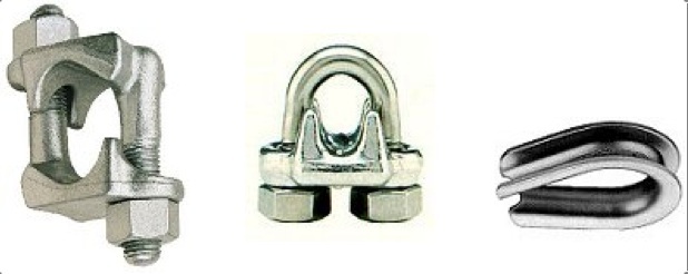
With the weight all the way down for measurement or for weighing, carefully check it for any structural problems--loose bolts, nuts, worn hooks, cracked plates, etc. If the weight is a rock, examine the embedded hook20. 19th century stonemasons very often set the hook in the rock with molten sulphur, which avoids dissimilar-metal electrolysis at the base of the hook. The danger here is that if the sulphur gets wet, the hook may be weakened by the action of the sulphuric acid which then forms. Some hooks are set with lead or zinc, metals which have a tendency to creep under a continuous load. Any looseness of the hook, cracks or spalling of the immediate area around the hole, or any other evidence that the stone/hook connection might fail is sufficient reason to remove the weight from service. A strong strap steel frame with a new hook will preserve the originality of the clock weight. While the weights are down, check the pulley(s) just above the weight. Old wooden pulleys should be carefully checked; they will probably need to be rebushed, and may be cut if they have been used with a wire rope. If the old pulleys are in such bad condition that they can't be salvaged, either cast-iron or cast-steel pulleys of an appropriate diameter should be installed. Also check the termination of the weight line--if it uses a thimble and U-clips (known as Crosby clips), make sure that they are installed correctly, and made of the proper materials. Correct installation and material information will be found later under the heading of Rope End Fittings. Also check the lubrication of the rope. The first few feet of weight line in the weight channel are rarely checked or lubricated, simply because they are usually located in areas with difficult access. More information on proper lubrication will be found under the heading of Lubrication:.
20 Some stone weights are made up of more than one section. The sections are held together by 'dogs'--shaped like a large staple--again, set with molten sulphur. Check the security of the dogs as well.23
Figure 11. An old granite weight with molten-sulphur-secured hook and a wood pulley used with wire rope. Note the visible wear in the groove of the pulley.
Why is it necessary to check the weights and pulleys on a tower clock? In one word, safety. If a weight line is to be replaced, you have to know the weight the new line must support. You may also find that the clock time train is seriously over-driven, whether deliberately, or inadvertently21. The time side weight is traditionally the lighter weight, whether the clock is an O.G. or a tower clock--but some makers threw tradition out the window, and the heavier weight will be on the time side. A simple visual examination should tell you whether an unscrupulous (or unconscious) repair type--I've seen it happen--has switched the weights, to cover a fault in 'repairs' to the time side. Usually the clock doesn't strike very well if this has been done, but then some tower clocks aren't allowed to strike at all, so this situation may go undiscovered for years22. Occasionally one of the driving weights has had extra plates or blocks, extra cubic feet of sand or gravel, or lengths of railroad track added for a similar reason--usually more weight than is needed to compensate for friction losses. The idea seems to be that if a small amount of extra weight makes the clock run well, then a lot is even better--never mind that the clock hasn't been cleaned in twenty years or more.
This "if a little is good then more must be better" syndrome is fairly common amongst clock custodians. It also appears when a clock is oiled: if a small amount of oil is good for the clock, then a lot of it ought to be even better. This is when oil gets poured on the wheels--car transmissions run in oil, don't they? They do, but those transmissions are designed with different tooth forms, they have different loads to handle, and don't have dust settling on them 365 days a year. At the opposite end of the oil spectrum is the electrified clock--most of them are oiled but once a year. A neglected, electrically re-wound clock was found to have six inch curls of dirt and dried oil extruded from the time train bushings when a local town complained that their clock didn't run very well. More weight was the custodian's solution to the problem; a solution which didn't work for very long. Or very well, either. This same custodian had tried to set the outside dial hands ahead by moving (and breaking off) the minute hand on the internal setting dial. It has been noted that the "if a little is good then more must be better" syndrome does not apply to the inspection of wire rope weight lines--they are usually ignored. The lack of inspection is not done with malicious intent; it is more likely that no one ever bothered to inform the custodian of the need to inspect the rope on a regular basis.
21 The alert reader will have by now noticed that the determination of the proper weight needed to drive a tower clock is almost invariably empirical. Variables such as the loading of the outside dial hands, degree of cleanliness of the clock, improper lubrication, the wrong type of weight line, too-small pulleys, etc., simply cannot be plugged into a single, simple formula. It is possible to derive the ideal weight to drive a tall clock (see Penman, Ppg. 34, 35), but weather and neglect (a dirty, poorly maintained clock) are unknown variables in a tower clock.
22 The author noted an innovative method for calculating the strike weight for a Holbrook tower clock in Vermont. The custodian had people of various weights hang from the weight line while he checked the action of the strike train. His petite wife, times two, plus 10%, was just right!24
Wire ropes:
Wire ropes are the current weight line of choice for most weight-driven tower clocks, usually because the
Figure 12. Typical construction of a 6 x 31 wire rope with a fiber core.
Illustration courtesy of Williamsport Wirerope Works, Inc.owner of the clock is looking for a longer lived, less expensive (in the long run), and safer system, or because wire rope was installed by the clock manufacturer. Properly installed and maintained wire ropes will last almost forever, but there are exceptions: witness the sitting judge in the Aroostook County Courthouse in Houlton, Maine, whose magisterial demeanor disappeared abruptly when his courtroom was the fleeting host to a 1300 pound strike weight which crashed through two floors and set off the building's sprinkler system when its wire rope broke23.
Figure 13. The three basic structural components of a typical wire rope.
Illustration courtesy of Williamsport Wirerope Works, Inc.The most common wire rope is known as Standard Coarse Laid Rope. Many sizes, grades, and classes of wire rope are made for special purposes, but a digression into these myriad types is not needed, simply because they are rarely used (or appropriate) on tower clocks, and are therefore not pertinent to this discussion. Wire rope is laid up in a helix, not twisted, from individual wires into multiple-wire strands, and these strands are then laid over a core to form the rope24. The most common construction is a right-hand lay, which is to say that the wires in each strand spiral to the left, while the strands spiral to the right. Left-hand lay is just the opposite, and Lang laid rope has both the wires in each strand and the strands spiralling in the same direction.
23 After he had changed his clothes and regained some of his composure, the judge announced that as long as he presided in that court, the strike side of the clock was not to be wound. Popular legend holds that some of the expressions the judge used are not to be found anywhere in the pages of Blackstone, but were a simple reversion to the non-technical and somewhat more direct and colorful speech of his French and Anglo-Saxon forbears. Little wonder.
24 The exception to this general construction is flat wire rope, made up of several 4-strand wire rope units stitched together with soft steel sewing wire.25
The rope core may be fiber (FC), wire strand (WSC), or independent wire rope (IWRC). Most wire rope today is preformed, which is to say that each individual strand is preformed into a helix, and thereby, each individual wire, before it is laid into the rope. Standard Coarse Laid Rope, 1/4 inch, 6 (strands) x 18 or 19 (wires in each strand), F(iber) C(ore), right-hand lay, is the rope almost invariably found on tower clocks, although it is occasionally incorrectly installed, on which more later. This rope has a relatively large number of small wires, thus serious attention should be given to whether the rope will be chafed or abraded in normal use, the intention being to avoid serious reduction in the strength of the rope. 1/4 inch, 6 x 18 or 19, fiber core, right-hand lay rope--the most common--(I've found it on an 1873 Howard installation), made with Improved Plow Steel (IPS)25, has a breaking strength of 2.75 tons. The rope weighs .1 pounds per linear foot. The rope that is finally chosen for the installation should provide a safety factor of at least five26. In other words, the maximum effective weight driving the clock should not exceed one fifth of the breaking strength of the rope. This means that the total load on any single part of a rope which has a breaking strength of 2.75 tons (5,500 pounds) in a multiple fall system should be no more than 1,100 pounds. Various grades of plow steel are used in the manufacture of wire rope, ranging from mild plow steel (2.07 tons), plow steel (2.4 tons) to extra improved plow
 Figure 14. The most commonly encountered wire rope structures. The bottom picture illustrates one lay of the rope as a unit of measure peculiar to wire ropes.
Illustration courtesy of Williamsport Wirerope Works, Inc.
25 Plow steels, in grades ranging through plow, mild plow, improved plow to extra improved plow, are high-carbon (.45 to .80%) steels, "made in an exacting process", used primarily in in the manufacture of wire ropes. Modern nomenclature is: for improved plow steel, Level 3 steel; extra improved plow, Level 4 steel; however, both nomenclatures may be encountered.
26 Federal regulations require that the rated load divided by the number of parts of rope (or falls) shall not exceed 20% of the nominal breaking strength of the rope; in other words, the safety factor is 5.26
steel (2.9 tons). Galvanized rope generally has a breaking strength that is 10% lower in each grade, and is not recommended. If the owners of a clock are assured that galvanized rope (which is more expensive) is safest, they are perhaps being gently misled into believing that the rustproofing eliminates any possibility that the rope will ever rust. Galvanized rope is indeed the least likely to rust, but most clock owners place such blind faith in the galvanization that the rope is rarely, if ever, inspected. The zinc coating may either wear or flake off the steel wire, which then begins to rust--usually inside the rope, where it cannot be seen. Stainless steel wire rope is also available, but is not recommended, simply because blind faith in so-called rust-proof wire rope may well result in finding the weight in the cellar with a busted bit of rope attached, because the rope was never inspected. It should be noted here that a wire rope with rusted wires in its core will require more weight to drive the clock. The roughened rusty wires are no longer able to slide easily past one another as the rope bends over a pulley, and the rust will abrade the internal wires when the rope is bent under a load. A symptom of a lack of lubrication, heavy loads, and small amplitude vibrations in the wire rope is known as 'rouging'. Rouging means that abrasion is occurring between the wires and strands, and that only small particles abraded from the wire are rusting.
Figure 15. An example of 'rouging.' The strands show nicked places caused by abrasion. Between the nicked places is an abraded area caused by wear between the strands and the fiber core of the rope. (For more detailed information, see under Lubrication:)
Illustration courtesy of Williamsport Wirerope Works, Inc.
27
The safety factor of five is used in the world of the rigger and the crane operator, whose operating cables undergo much more severe stresses and strains, as well as constant exposure to the elements. Careful consideration of the construction and design of the weight system may make it possible to use a lesser grade of rope, and less expensive pulleys. However, better safe than sorry--don't ever rig a weight system with a rope (or pulley) safety factor lower than five.
The weight the rope will support must be known before a proper selection can be made. In making the final choice the following rope properties should be considered: strength, which is a function of grade, size, construction, and core material; flexibility and resistance to fatigue, which are both greatest in ropes with a large number of small wires, ropes with a fiber core, Lang laid ropes, and ropes which are pre-formed; abrasion resistance, which is better in ropes made of larger wires, but which varies somewhat according to the rope's construction; crushing resistance, which is greatest in wire strand or independent wire rope cores. Flexibility and resistance to fatigue criteria are second only to breaking strength in requirements for a tower clock, since there is little likelihood that the rope will be abraded or crushed if it is correctly installed.
Figure 16. An illustration of a crushed wire rope.
Illustration courtesy of Williamsport Wirerope Works, Inc.An extra flexible rope, even though it will be more expensive initially, should be seriously considered if the clock winding barrel diameter is too small. The selected rope size (diameter) will have to be considered in the selection of pulley sizes and materials.
28
Proper installation of the wire rope is critical to its weight carrying ability, its life, and the overall safety of the system. The rope should not be kinked, which will seriously weaken it. Any kinked rope (even if it is brand-new) should be immediately discarded, and replaced with new, unkinked rope.
Figure 17. an illustration of a wire rope that has been used after being kinked..
Illustration courtesy of Williamsport Wirerope Works, Inc.Don't try to splice in a new section of rope, it is not a safe practice. It's a good idea to call the clock owner's attention to kinked ropes, because they aren't safe. To correctly install a new wire rope, it's best to reel the new rope onto the clock winding barrel from the supply reel (this avoids twisting the rope), making sure that the cable goes on the winding barrel bent in the same direction as it was on the supply reel. If a pre-cut length of rope is supplied in a coil, the coil should be unrolled along the floor as it is wound on the winding barrel, again making sure the rope is bent in the same direction on the winding barrel as it was in the coil. Bending the rope in the opposite direction stresses it unnecessarily. The rope must also have the proper construction, or lay. If the rope passes over the top of the barrel as it is wound on the barrel (an overwound barrel), a right-hand laid rope must be fastened to the right-hand side of the barrel, and a left-hand laid rope must be fastened to the left side of the barrel. If the rope passes under the barrel as it is wound on (an underwound barrel) a right lay rope must be fastened to the left side of the barrel and a left lay rope must be fastened to the right side of the barrel.
29
Disregard of (or more likely, a lack of information about) this requirement is the reason many clocks have the wrong type of wire rope--it has the wrong lay--on their winding barrels. (The same criterion applies to household clocks as well, but is not quite as critical.) A rope with the wrong lay with regard to its attachment point on the barrel will not spool on and off the barrel as smoothly and evenly as it would if it had the correct lay, because successive wraps will tend to chafe against one another. Check the winding barrels and their attachment points before you order the wire rope, or make sure the rope is correctly attached to the barrel according to the rules for over- or underwound barrels. Try to avoid any reverse bends in the rope during installation, and in reeving (stringing) the pulley system, because a reverse bend stresses the rope unnecessarily. Reverse bends may be impossible to avoid simply because of constraints imposed by the construction of the building in which the clock is housed. If a reverse bend in the rope is necessary, then do the best you can, with a large diameter pulley at the point of the reverse bend, and very seriously consider using an 'Extra Flexible Hoisting Rope'.There are so many different types of winding barrels, ranging from wood to cast-iron, with so many different methods of attaching the wire rope to the barrel that the best course of action may be to ask someone who is familiar with wire rope how best to attach the rope to the barrel. Socketing or clamping the rope are considered the ideal methods. (If a wire rope is to be installed on a wood barrel, the wood should first be covered with sheet metal, because the wire rope will cut the wood surface.) Most companies selling wire rope are quite free with all sorts of good advice--just make sure that your source of information is not a salesman who has a mere smattering of knowledge and is looking for his commission--remember, an expert is usually a salesman 100 miles away from his home office. The best means of terminating a wire rope for attachment to a barrel is a ball (which fits in a cavity in the barrel) swaged or zinc-soldered on the barrel end of the rope, but this may interfere somewhat with reeving (stringing) the line.
30
The line may also be securely clamped to the surface or the flange of the barrel, but tying a knot in the end of the line (which reduces the breaking strength by 20%), or nailing the rope to the barrel are not recommended. A wood barrel may have a hole bored all the way through the barrel, with a socket cut to accommodate the terminating device. A hardened two-piece ball for the barrel end of the rope is available. An outer casing is slid over the end of the line, and a conical wedge is then driven into the center of the line, to trap the strands against the outer casing; however, this termination will reduce the breaking strength by at least 20%. It is always a good idea to be sure that at least two wraps of weight line are left on the winding barrel when the weight is all the way down--preferably three. The friction of the line wrapped on the barrel and the tangential angle of pull help to keep the barrel end of the line where it belongs. A weight line pulling radially from the surface of the barrel because the line is too short will usually pull the end out of, or off of, the barrel, more often than not with rather dire consequences. Standard crane practice is a minimum of "two full wraps remaining on the drum with the hook in its extreme low position."Most tower clock installations route the line weight from the barrel to a (usually) conveniently (sometimes, apparently randomly) located lead (or first) pulley to redirect it toward the top of the weight channel, where another guide pulley may be found. The proper location and the alignment of this first pulley are critical to the maximum life of the weight line, and to the even winding of the line on the barrel when the clock is wound. The centerline of this guide--or more properly, fleet--pulley should be aligned with the centerline of the barrel. When the weight line is at either extreme end of the winding barrel, the fleet angle (which is the angle between the pulley/barrel centerline and the wire rope at its extreme deflection) should not exceed 2°. 1 1/2° is the preferred maximum angle; 1/2° (or 30 minutes) is the preferred minimum angle. A 1 1/2° fleet angle allows the line to spool evenly on the barrel without any separation between turns, and avoids interference with, and possible damage from, the sides of the groove in the pulley. Anything less than a 1/2° fleet angle will tend to make the line bunch up at one end of the barrel.
31
Figure 18. Fleet angle diagram.
The fleet angle should be limited to 1 1/2° if the winding barrel is smooth, no more than 2° if the barrel is grooved. If the lead pulley must be installed very close to the clock, due to space constraints, use either a pivoted 'fleeting pulley' which can swing from side to side, or a 'fleeting sheave'; a grooved wheel mounted on a horizontal shaft. Both the fleeting pulley and the fleeting sheave must be mounted close enough to the drum, or so constructed that a minimum 1/2° of fleet angle is provided at maximum 'layover' of the fleeting pulley, or maximum lateral deflection of the fleeting sheave on its shaft. Don't try to use either the pivoted fleeting pulley or the fleeting sheave to change the direction of the line to lead it to the top of the weight channel--use another pulley farther away from the clock. A misaligned or misplaced fleeting pulley or sheave may cause the successive turns of line to chafe as they wind on or off the barrel, or will chafe the line on the edges of the pulley groove, both of which wear the line unnecessarily. Calculating the fleet angle is rather simple--no higher mathematics are involved--because someone else already did it for you. Merely divide the depth (some call it width) of the winding barrel by 2, and then divide this figure by .03527. An 18 inch (1.5 foot) deep barrel, divided by 2 is .75 feet. .75 divided by .035 equals 21.43 feet. The rule of thumb in the crane operator's world is 1.25 feet of separation between the barrel and the first, or main, pulley for each inch of barrel depth or width28. If the fleet angle is too great, the line tends to bunch up in the middle of the barrel, and may chafe on the sides of the pulley groove when the line is forced toward the side of the barrel. Too small a fleet angle will allow the line to bunch up on one side of the barrel, or the line will
27 Trigonometrically, you're solving for the adjacent by dividing the opposite (1/2 the drum width) by the tangent of of 2 degrees (.03492, rounded to .035).
28 Note that this rule of thumb calculation uses the entire width of the barrel, not one half of the barrel as in the trigonometric calculation.32
Figure 19. Typical fleeting pulleys and fleeting sheave..
chafe against a preceding turn as it spools on the barrel. The majority of tower clock installations don't have correct fleet angles, simply because there isn't enough room available in most steeples. Most clock rooms and steeples are a lot less than 21 feet wide, and many have limited space below the clock room floor. The best advice is to do the best you can with a pivoted pulley or fleeting sheave, and to watch the line during winding, to make sure it winds across the barrel as evenly as possible. Either the fleeting sheave or the pivoted pulley work very well, although some clock owners will complain at the extra cost. Remind them that it is a safety consideration, and that busted ropes can mean busted budgets. Tell (many times!) the custodian that it is not ever a good idea to try to guide the line onto the barrel with his fingers; his fingers will likely be stabbed by a broken wire, and if he somehow (these people can do some weird things) manages to get his fingers trapped by the line, it's going to be a bit difficult for him to release the ratchet to unwind the cable and release his fingers.
Rope End Fittings:
Clamping the end of the cable to form a loop, or eye, at the dead end (away from the barrel) also has its rules and proper methods. If a Crosby clip (U-bolt clip) is used, the saddle of the clip should bear on the live (weight-bearing) part of the rope, and the U (or bolt) portion on the dead part. The U-clip saddle must be made of forged steel. Installing the bolt on the live portion of the rope may cut or kink the cable, which poses all sorts of dangers. For 1/4 inch cable, two 7/32 inch clips must be used, spaced at least 3 1/2 inches apart. The nuts on the U-bolts must be re-tightened an hour after the wire rope is put under load, because the rope will stretch--and its diameter will decrease toward the nominal.
33
The fist clip is recommended, as it will not cut or kink the wire rop. A clamped eye (any eye) must always use a thimble. The strength of a properly made eye (with fist or Crosby clips) is rated at 80% of the nominal breaking strength of the rope; something to consider when figuring the safety factor and the total load on the rope. In practice, any cable termination, other than a swaged or zinc-soldered termination29, must be assumed to have only a strength rating of 80% of the rope's rating, therefore, calculate your safety factor accordingly. For instance, the load rating of the rope under discussion (Standard Hoisting Rope, 1/4 inch, 6 x 18 or 19, FC, right- or left-hand lay) drops to no more than 875 pounds with any termination other than those which are properly swaged or soldered. Remember that courtroom in Maine.
Safety Considerations:
After replacing a rope, and before you leave the clock room, it is a good idea to wind the drive weights all the way up, let them all the way back down, and then rewind the clock again to make sure the ropes wind on and off the barrels evenly and that the ropes are correctly rove through all the pulleys. Also check for a condition called 'block twisting' or 'cabling'. When the wire rope is first loaded, it may tend to untwist or unlay slightly, and then take a set. When the rope is later unloaded, the pulley assembly at the weight may twist--up to 180°--which may tend to tangle the ropes. (This may also happen with the rope loaded.) Merely rotate one end or the other of the rope a turn or two (the apparent 'twist' will be reduced or eliminated), load the rope and wind the weight all the way up and then back down, and check for any evidence of 'cabling'. Repeat as necessary. It is possible to use a suitably strong turnbuckle just above the weight. The turnbuckle can then be adjusted to remove any of the effects of cabling.

(Any time the weights are let down--which puts all of the weight on the winding crank--have an assistant with you in the clock room to release the ratchet[s]. Don't try to do it all alone. Too many things can go wrong.)
29 Swaged (compressed) fittings should always be applied as recommended by the rope manufacturer. Soldered fittings are always applied to properly cleaned rope with pure zinc solder or babbit metal. In some instances, the use of thermo-setting resins is permitted, but the socketting must be done correctly. Once again, follow the rope manufacturer's recommendations. His good reputation depends to a great extent on his good advice.34
Make sure that the ropes or the winding barrels are clearly marked to prevent overwinding and the consequent possibility of damage to the pulleys, the rope and the clock. Paint doesn't work well as a marker on wire rope--it splits off the strands as the rope runs around the pulleys. Tape may last a bit longer, but has to be renewed rather often. It is not a good idea to open (birdcage) the strands to insert a marker that is woven or interleaved into the strands. Lord Grimthorpe suggests a positive stop, which has some dangers of its own if the winder isn't paying attention, or an electrical alarm of some sort to alert the winder that he is at the end of his rope, so to speak, which is probably the best idea. Consider the clever soul in New Jersey who recently took an electric impact wrench up to the clock room, popped the socket on the winding square, pulled the trigger, and reeled in all of the weight line, except for the part that broke off and followed the weight all the way down.
While you are working with the ropes and the weights, always remember (and think about) where the downward flight path of the weights will take them should the rope break. It is a good idea to have a catch box (about 3 ft x 3 ft x 2 ft high) filled with rocks--not sand or gravel--under the weight to absorb the force if the weight falls; it's even better if the weight can fall all the way to solid ground. If the weight channel ends above a normally inhabited area, the floor directly under the weight should be seriously reinforced (preferably under the supervision of a professional engineer), a rock-filled catch box installed, and/or a stop cable attached to the weight--anything that will prevent shorter people and longer weight chutes. While you're pondering the flight path of the weights, take a long, hard look at the pendulum. Many of these particular weights have been swinging on the same suspension spring for over one hundred years, and that spring might be on the verge of failure.
35
The worst 'repair' to a suspension spring I've seen yet involved a section of hacksaw blade--with the teeth still on it--suspended on a nail. I still have it, and I may frame it. It worked--for a very short while--but fortunately there was a very solid floor underneath the pendulum. Most pendulum enclosures I've seen will merely provide a momentary check to the pendulum, after which the acceleration of gravity will again take over at 32 feet per second per second. A 100 pound pendulum falling through 20 feet is capable of delivering a hammer-blow of 2000 foot-pounds. That's more than enough to punch through the typical attic floor and the ceiling below, and is guaranteed to ruin someone's day. A stop pin, or a stop cable attached to the pendulum is recommended.
Electrical Safety Considerations:
Run, don't walk, away from a clock installation that has electrical wires sharing the weight channels. That is a fire looking for a place to happen. If weights are moving up and down the channels, the wires must be removed, even if the wires are encased in conduit. The electrical code may allow conduit-enclosed fire or intrusion alarm wiring (low voltage) in the weight channel in some areas, but it is not a good idea in any case. Check with a state licensed electrician or a fire marshall--there's just too much at stake.
An electrically rewound clock should be checked carefully: many of the potential dangers that are specific to manually wound clocks will also appear. Remember that most, if not all, of these clocks were wired long before a National Electrical Code appeared. If the motor wiring or the switch wiring (or any of the wiring in the clock room), appears to show signs of obvious age and need of attention, recommend to the owner of the building that the system be rewired. It pays to be rather blunt about this, even if you lose a job, particularly if the clock owner claims the installation is grandfathered.
36
Grandfathering in a case like this is immaterial and irrelevant--an unsafe electrical system is still an unsafe electrical system--there is just too much of a possibility that something will go wrong while you are working on the clock, or during the warranty period. I, for one, don't want to be responsible for the loss of a building on the National Historic Register (or any building), much less another tower clock. These electrically re-wound clocks should also be checked for possible problems with both pendulum bobs and driving weights. In most cases, the weights are suspended on chains--some of which have been in use for over 70 years. A thorough cleaning and a link-by-link examination of the chain is in order. These chains will stretch, to the point that they no longer fit the sprocket(s) on which they ride. You may (probably will) have to get a new sprocket, and chain. Motorcycle drive chain with a breaking strength of at least 1000 pounds is recommended. Lubricate the chain with a synthetic, silicone-bearing penetrating lubricant, whether the chain is the original or a replacement. Reinforcement of the clock room floor may be called for, or the installation of a catch box or a stop cable for the weights, depending on the configuration of the weight system. The action of the rewind start and stop switches should be carefully checked. Switches on a 70 year old installation may be the originals, very likely with badly worn contacts, and should probably be replaced. (Some of these old switches actually used slate as an insulator.) If the clock dials are illuminated, check the switches which control the lights; check the switch actuator, and check the electrical wiring. If there is no fuse-box or circuit-breaker box in the clock room, insist that one be installed before you do any work on the clock. It is dangerous (to you, to the electrician replacing a rewind motor, or to the custodian changing a light bulb) if it is necessary to go all the way down to the main breaker box, shut off the breaker for the clock, hang a tag on the breaker, and go back up to the clock room. Building custodians (particularly in a public building) have a tendency to forget that someone is working on the clock, and have been known to ignore warning tags on breakers, simply because the breaker also controlled another circuit someone else wanted to use. I've seen a church clock which had evidently been rewired by someone within the church--obviously someone who was not familiar with (or ignored) Code --that would give an electrician a seizure. The rewind circuits had been rewired with zip cord. Zip cord is a 'technical' term for a household extension cord.Worthy of mention and caution on these electrically re-wound clocks is the danger associated with the rewind gearing system. These gears are driven by a high-speed electric motor, and via the gearing down, exert tremendous torque. Keep your hands away from these rewind gears while power is applied to the rewind system.
37
Wire Rope Inspection:
OSHA has developed various checks and guidelines which will be, if they haven't already been, applied to tower clock weight line systems, and their proper rigging. One of these involves checking the rope for broken wires by running a shop towel along the cable. Any snag indicates a broken wire. If you do this check, please don't do it with your bare hand! Rope replacement is a given if the wire rope on a crane has any of the following defects (and the same standards should apply to a clock weight line):
1. 1 (one) valley break. A valley break occurs at the wire/core interface, and indicates poor or non-existent rope lubrication, and excessive wear at the wire/core interface of the rope. Lubrication will not correct the condition.
2. In running ropes, six randomly distributed broken wires in any one lay, or three broken wires in one strand of one lay. (One lay is that part of rope in which a specific strand makes one full turn around the core.):
3. Kinking, crushing, birdcaging, reduction in rope diameter, or any other damage resulting in distortion of the rope structure:
4. Wear comprising one-third of the outside diameter of outside individual wires: 5. One outer wire that has broken at its contact point with the core of the rope and protrudes or loops out from the rope body:which seem to be good guidelines for those working with tower clocks. Pulleys will be inspected, and the owner of the clock will have to replace any that are too small in diameter, incorrectly installed, or otherwise incorrect. Ratchet wheels and pawls on the clock will also be inspected for excessive wear and free operation. The custodian, or you as the clockmaker, should inspect the entire weight line on a regular basis, and that means inspect the entire line, not just that visible portion that reappears on the barrel every week.
38
Crawling or tight-roping along a ceiling joist into the corner of an attic whilst wiping a towel along the rope, and simultaneously trying to avoid falling through the ceiling isn't at the top of anyone's 'To Do' list on a mid-summer afternoon, but the greatest wear, and the greatest possibility of damage to the rope is always off in a dirty and inaccessible corner. Corrosion is an insidious enemy of wire rope. A wire rope may show little external evidence of damage, yet the inside may be seriously rusted because it was never lubricated. Do your inspection on a rainy day, and check the roof for leaks (particularly over the weights) at the same time. It's good P. R., and will be very much appreciated by the clock owner.Clock Room Safety Checks:
You may also want to remind the custodian and the clock owner that OSHA doesn't like to find bird droppings on and around the clock. Co-residents such as bats and birds are not welcome in the clock room, regardless of OSHA--they spread various unwelcome diseases to clockwinders and clockmakers--their droppings can be very abrasive, and can react chemically with clock metals. In the Northeast, I've noticed that cluster flies will crowd into a clock room in the fall, and crawl all over the clock. Many of them meet their doom in the teeth of the wheels, to the detriment of the teeth, because insect exoskeletons are also rather abrasive. Don't try to keep the cluster flies out--it's impossible--but try to keep the wheel teeth and pinion leaves clean. Steeples and clock rooms should be sealed to keep larger vermin out, and any areas used in normal maintenance of the clock should be cleaned up. If the clock room is not clean, OSHA may well tell the clock owner to clean it, or shut it down. Bird and bat droppings are a distinct health hazard to everyone, particularly to the clockmaker who has to work in an area where he may breathe in or otherwise ingest viral or bacterial infectors. Psittacosis is no fun whatsoever. The Mercks Veterinary Manual (5th Ed.) states that "The disease occurs worldwide...Aerosols and dusts from respiratory discharges and digestive dejecta (pigeon poop) are infective." A mask is recommended in the work area--it's much less expensive than treating psittacosis--as are a bath and change of clothes immediately after leaving the work area.
39
Lubrication:
Lubrication of the wire rope is a necessity. Lubrication will retard corrosion, and decrease friction and wear by allowing the wires and strands which make up the rope to slide past one another as they bend around a pulley or winding barrel. The lubricant prevents metal-to-metal contact and prevents corrosion. The simplest and quickest check is to rub a finger in the groove of a pulley. If no lubricant is apparent, the need for lubrication is immediate. Lord Grimthorpe recommended a lubricant (to be worked into the strands by hand!) made up of tar and grease. Somehow, the author has the feeling that this lubrication method will not find much favor with fastidious clock custodians, particularly those whose clocks have wood winding barrels. Some modern wire rope lubricants are nearly solid, and have to be heated to 160 to 200 degrees F., or thinned with gasoline, before they are applied to the rope. Needless to say, none of these lubricants are recommended for use in any steeple or in the clock tower of any building!
The desired end result in lubricating a wire rope is to get the lubricant into the core of the rope, that the various wires which make up the rope can slide past one another as the rope bends over a barrel or a pulley. A lubricant-impregnated fiber core will help a great deal in preventing corrosion. Modern recommended lubricants for crane ropes are a heavy oil or a grease carrying either molybdenum disulphide (preferred; also known as MOS2) or graphite. It is unfortunate, but both of these lubricants are very dirty. MOS2 usually has to wear off if you get it on your hands, and clothes stained with it are stained forever. Graphite isn't very far behind. If something cleaner is preferred--and it usually is--the heaviest grade of Mobil 1 (a synthetic oil) has been recommended for wire ropes. This particular brand of oil, in a lighter grade, is also used as the lubricant of choice for the pivots on a tower clock. After extensive reading in the literature, my conclusion is that the wire rope system for a clock is most similar in general requirements to that of an elevator.
40
Both are protected from the weather, both require frequent inspections, and the failure of either system can be rather dangerous. Perhaps the simplest means of maintaining the proper amount of lubricant on a wire rope is with a felt pad, wick-type lubricator. Although this method will not oil those parts of the rope off in a far corner of the attic, it could be placed so the usually hard-to-reach portions of the rope are kept oiled. Williamsport Wirerope Works, Inc., recommends a light viscosity Spindle oil30.More and more clockmakers who work on tower clocks are using synthetic motor oils. These oils have very wide temperature ranges, and don't tend to dry out and gum as rapidly as do mineral oil-based lubricants. An industrial spray lubricant carrying MOS2 is available, but evidently only in 55-gallon drums. If you don't absolutely have to carry something (a 55 gallon drum!) up to the clock room, leave it below. It is difficult to make any specific recommendations on oil application methods, because there are so many different clock weight line configurations, but the felt pad, wick-type lubricator is probably the most effective. However messy the lubrication job might turn out to be, it is necessary to the life of a wire rope. It is also a safety procedure, and safety is of primary importance in any work with tower clock weight line systems.
A word of caution. Many of the old tower clocks use winding barrels made of oak. Oak has a tendency to react chemically with some mineral oil-based lubricants. Various articles in past issues of the BULLETIN caution against oiling unbushed pivots in a wooden works clock for this reason. It is strongly recommended that any wood barrel be covered with sheet metal to avoid this possible reaction, and to keep the cable from cutting the surface of the winding barrel.
30 Light viscosity' is calculated to be a Saybolt Seconds Universal (SSU) viscosity rating of 34 to 38 seconds at 210 degrees F., which equates roughly to a 10 weight oil under the more familiar API (SAE) viscosity ratings.41
Probable Trouble Spots:
The first check on a weight drive system should start at the clock. Likely areas of trouble will be:
1. Improper termination of the weight line at the winding barrel.
2. Wrong D/d ratio for the winding barrel diameter/rope size.
3. Improper lay of the rope, i.e., right hand lay attached at the left side of the barrel (overwound barrel); left hand lay attached at the right side of the barrel (overwound barrel). The lay and the connection points are just the opposite with an underwound barrel. Also wrong type, grade, or rope size.
4. Incorrect fleet angle between the winding barrel and the first, or lead, pulley.
5. Insufficient diameter (D/d ratio) of pulleys in the weight line system.
6. Dirty, improperly lubricated pulleys, or pulleys made of inappropriate materials.
7. Lack of lubrication of the rope and resulting rust.
8. Loose weight hooks and/or improper connections to their pulleys/lines.
9. Inappropriate and unsafe flight paths for the weights, (and the pendulum) i.e., the floor beneath the weight is inadequately reinforced, the weight of the pendulum will not be supported by its enclosure/stop pin/stop cable.
10. Uninspected weight lines (most common if a galvanized or stainless rope has been installed).
11. Weight line too short, rope terminator may pull out of or off of, winding barrel.
12. Badly worn, or binding ratchets on great wheels/winding barrels.
13. No warning markings on the weight line, or no alarm to warn that weights are all the way up.
14. Excessive weight after the system has been redesigned with low friction pulleys, etc.
42
15. Switched weights (the time side is usually the lightest [smallest]).
16. The custodian. This is usually the source of most clock problems. Historically, most custodians (and clock owners) are ignorant of any safety precautions; custodians are (usually) grossly underpaid; and almost invariably totally horologically ignorant. A maintenance guide and clearly written instructions may help to remove most of this particular potential trouble area. Emphasize to the clock owner that it is best that only one person be charged with care of the clock. An excess of ignorant (however well-meaning) hands have been known to result in damage to the clock, the building, and to the well-meaning hands.Do not construe the above to be the last word in safety considerations or in design criteria for tower clock weight systems. There are so many different installation requirements and restrictions that no one article can possibly cover all situations. I do recommend that you become familiar with the ANSI and OSHA requirements for the installation, care and maintenance of wire rope systems, and use a lot of common sense. Make sure that the clock custodian is aware of what he has to do to properly care for and maintain the weight drive systems. I have found it a good (and very much appreciated) practice to compile a maintenance document which covers oiling and greasing instructions for the clock and bell strike mechanisms; for the inspection and care of the weight drive system; inspection of automatic rewind systems, and precautions for all of the systems used in a particular installation for the custodian of each tower clock installation. These instructions are always provided as a part of my contract in any bid I make on any tower clock. It has been my experience that word-of-mouth instructions on the care of the clock become garbled over the years, or are simply not passed on to the new custodian. The instruction sheet provided by many clock manufacturers is totally inadequate today, since tower clocks no longer figure so prominently in our lives, and there is so little in the literature to which the custodian, or, indeed, the clockmaker, can refer for assistance.
43
In short, use common sense, ask questions (a local rigging company is a good source for information--they work with weights and wire ropes daily in all kinds of weather and are familiar with the requirements and codes), and ask for help if you don't know the solution to a problem. The only stupid question is the one you didn't ask.
Oh, the snatchblock? That's a block with one removable cheekpiece, so the pulley can be located in the middle of a cable already solidly fastened at both ends. Also known as a gateblock. Very handy for the poor soul who has to thread a wire rope through all those pulleys.
THE BITTER END Acknowledgements:
My special thanks go to Williamsport Wirerope Works, makers of Bethlehem Wire Rope®, for permission to use their data and illustrations in this article, thanks to Sam Ledbetter for his advice and suggestions on cable lubrication, to the Balzer Family for sharing their expertise, to Frederick M. Shelley for encouragement, and to the local churches who let me work on their clocks.
Suggested further reading:
ANSI Standards:
ANSI/A11264.1 Stairs and Railings (for information only, but it might be a good idea to bring this standard to the building owner's attention.)
ANSI/SAE J881-OCT80, Lifting Crane Sheave and Drum Sizes.
ANSI/SAE J959-MAY91, Lifting Crane Wire-Rope Strength Factors.
Combined Federal Regulations (CFR) Chapter XVII, ß 1910.179-.183, ß1926.550-.554
Federal Specification RR - R - 571a; Minimum pulley and rope diameters.
U. S. Simplified Practice Recommendation 198-50. (Maximum rope loading.)
Machinery's Handbook, 24th Edition: Ppg. 323 - 339.
_____________________
44
APPENDIX I: CABLES BIBLIOGRAPHY
AKED, Charles K., Gravity Drive in Large Clocks: BULLETIN of the NAWCC, #261, August, 1989
GORDON, G. F. C., Clockmaking Past and Present: The Technical Press, Ltd., London. 1928.
GREEN, Robert E., Ed., Machinery's Handbook, 24th Ed.: Industrial Press, Inc. 200 Madison Avenue, New York, NY 10016.1992.
PENMAN, Laurie, M.B.H.I., Clock Design and Construction: ARGUS BOOKS LTD, Wolsey House, Hemel Hempstead, Herts, England,. 1984.
SHAPIRO, Howard I., P.E. Cranes and Derricks: McGraw-Hill Book Company. New York. 1980.
SIEGMUND, Otto H., Ed., The Merck Veterinary Manual, 5th Ed.: Published by MERCK & Co., Rahway, New Jersey. 1979
COMBINED FEDERAL REGULATIONS (Chapter XVII ß 1910.179 -.183, ß1926.550 .554) of the United States Government. Government Printing Office, Washington, DC. 1994.
WILLIAMSPORT WIREROPE WORKS, INC., Wire Rope Catalogs and Technical Bulletins: Williamsport Wirerope Works Technical Staff. Privately printed, 1992.
APPENDIX II: Formulas
Should anyone find an error in any of these formulas, or a lack of clarity as to their intended use, please . While I don't have the expertise of the late Donn Haven Lathrop, I will do my best to resolve your concerns. / CSZ / Nov.2017
1. Weight Drop, Compounded:
Cvd = Tvd x (1/F) where:
Cvd is compounded drop, in feet;
Tvd is total weight drop required, in feet;
F is the number of falls.
The reader must be reminded that the sheave(s) take up a finite amount of space above the weight, a space that must be taken into consideration in calculating the required weight drop.2. Mechanical Advantage:
1. The accepted definition of a mechanical advantage is the ratio of effort to resistance, or, MA = R/E ; however, to compute a mechanical advantage ratio (really a disadvantage ratio, in that more weight is required with multiple falls), which is necessary to derive the total weight required in a compounded weight drive system, a permutation of the formula is required. Counting the number of falls at the weight and multiplying the design weight by the number of falls yields the same result.3. D/d ratio; which is the ratio of the sheave (or winding barrel) pitch diameter to the diameter of the rope;(It must be remembered that this is a simple solution; no allowance is made for frictional losses and bending loads.)R = FE, where:
R is the total weight required, in pounds;
F is the number of falls;
E is the actual weight required to drive the clock, in pounds.2. The mechanical advantage of a winding jack, wherein a smaller gear (pinion) drives a larger gear is;
MA = Dt/Pt, where;
Dt is the number of teeth on the driven gear, and;This is only the MA of the winding jack itself: the total mechanical advantage must also include the length of the winding handle, and the diameter of the winding barrel.
Pt is the number of teeth on the driving pinion (gear).
D = (X d), where;3A. How does one calculate the D/d ratio?
X is a manufacturer/federal specification constant for differing sizes and constructions of wire ropes, and;Pitch diameter is the pulley tread diameter plus one half the rope diameter.
d is the diameter of the rope in inches.
Add the diameter of the drum barrel to the diameter of the wire rope you want to use. Then divide by the diameter of the wire rope.4. Bending stress: sb = Edw /D, where:
Example: When using 1/2" wire rope on a 10.75" drum barrel.
10.75 + .5 = 11.25. 11.25 divided by .5 = 22.5:1 D/d ratio. This meets the ANSI/ASME recommendation of 15:1 for pulling and 18:1 for lifting applications.
sb is in pounds;5. Bending load; pb = sb A; where A = d2Q; where:
E is the modulus of elasticity of the wire rope, which varies between 1 x 10⁷, and 1.4 x 10⁷.
1.2 x 10⁷ (12,000,000) is a frequently used average value;
dw is the diameter of the component wire (for 6 x 19 rope, dw is .063d);
D is the pitch diameter of the pulley in inches.
To calculate bending stress; sb, in the outer wire(s), and the bending load; pb, use these formulas:
sb = Edw /D, for bending stress; andE is the modulus of elasticity of the wire rope, which varies between 1 x 10⁷, and 1.4 x 10⁷ . 1.2 x 10⁷
pb = sbA; where A = d2Q.
(12,000,000) is a frequently used average value. d is the rope diameter; dw is the diameter of the component wire (for 6 x 19 rope, dw is .063d); D is the pitch diameter of the pulley in inches; A is the metal cross-sectional area of the rope; and Q is a constant derived for a specific type of rope. For 6 x 19 wire with a fiber core, Q is .405.
pb is in pounds;
d is the rope diameter;
A is the metal cross-sectional area of the rope; and
Q is a constant derived for a specific type of rope. For 6 x 19 wire rope with a fiber core, Q is .405.N.B. In both 4. and 5. above, constants such as dw, A, and Q, are provided by the rope manufacturer.
6. Radial pressure on a pulley or a barrel: P = 2T / (D d) , where:
P is radial pressure in pounds per square inch;7. Calculating weight of solid stone driving weights: W = (h x d x w x 160) / 1728, where:
T is rope tension in pounds;
D is tread diameter of barrel or pulley in inches;
d is rope diameter in inches.
W is in pounds, and;8. Fleeting pulley/sheave placement;
h, d, & w, are in inches;
1728 is cubic inches in a cubic foot;
160 (lbs) is an empirically derived constant (see text).
Fsp = barrel depth/2 x .035, or;
Fsp = barrel depth x 1.25 (ft.), where;
Fsp and barrel depth are in feet.[Editor's Note: Numbering of these formulas is Donn's original; "8" was duplicated.]
8. To compute the effort and resistance of a lever, as in a barrel/great wheel:
Lea x R9. To compute frictional losses due to pulleys and wire bending loads:
Lra E
where:
Lea is the length of the effort arm;
Lra is the length of the resistance arm;
R is the resistance (usually in pounds), and;
E is the effort (usually in pounds).
P = W/r where
P is the force at the winding drum,
W is the weight (in pounds) of the driving weight
r (to compute frictional losses in rewinding the clock [lifting the weight] ) isr = (1 - µ)m + 1 + (1 - µ)m + 2 +. . . + (1 - µ)m + n
wherem is the number of 180° bends the rope makes at the weight;r (to compute frictional losses in driving the clock [weight falling] ) is:
n is the number of parts of line.
µ is the loss coefficient (friction due to pulley bushing[s]),
expressed as a percentage, e.g., with a 2% friction loss; µ = .02.
r = ___1____ + ___1___ +. . . + ___1___ (1 - µ) m + 1 (1 - µ) m + 2 (1 - µ) m + n An example: Assume a 50 pound weight is needed to drive a clock, requiring a triple fall (3 part) compound system:
Simple solution, disregarding r (no friction component): 50 x 3 = 150 + 10 (pulley weight) = 160 pounds; therefore 160/3 is 53.333 lbs. The weight itself must weigh 47.666 pounds.
The complex solution:
Winding the clock: Let µ = .02, m = 1, and n = 3
1 - µ = .98, therefore: r = .982 + .983 + .984
(this is: .98 squared; plus .98 cubed, and so on.)
therefore:
P = 160 / 2.82 = 56.74 lbs. (effective resistance to rewind effort)
Driving the clock:
or:
r = ___1____ + ___1____ +. . . + ___1 ___ (1 - µ) m + 1 (1 - µ) m + 2 (1 - µ) m + n
r = ___1___ + ___1___ + ___1___ = 3.18 .982 .983 .984 P = 160 / 3.18 = 50.32 lbs. (effective driving weight required)
These figures are ideal calculations--no real world modifiers such as a lack of lubrication, loading of the external hands, etc., are involved in the calculation. Still rather empirical, isn't it? We are, however, getting close to being able to determine the theoretical required weight to drive the hypothetical clock. Note, however, that it does take more effort to rewind a compound weight system.
10. To calculate the maximum length of rope (L) that can be wound on a winding barrel:
L = (A + D) x A x B x K, where:
A = nominal rope diameter,
D = diameter of barrel, inches,
B = width (or depth) of barrel, inches
K = appropriate factor from table below:
Rope Dia. (in) Factor 3/32 (.094) 23.4 1/8 (.125) 13.6 3/16 ).1875) 6.14 1/4 (.25) 3.29 5/16 (.3125) 2.21 3/8 (.375) 1.58 7/16 (.4375 1.19 1/2 (.5) .925 11. To calculate the theoretical maximum length of rope which can be wound on a barrel:
L = (D x pi) x (B/A) — 12, where:
D = barrel diameter, inches
pi = 3.141592654
B = width of barrel, inches,
A = nominal rope diameter
APPENDIX III:
Glossary of wire rope terminology.ANSI: The American National Standards Institute, from whose criteria the OSHA standards for safe operation of cranes and derricks and other systems using wire rope isntallations are derived.
birdcaging: An expansion of the strands laid into a rope; usually caused by twisting against the lay (q.v.).
block: A system of sheaves (q.v.) sharing a common frame, and (usually) a common axle.
compounding: A system of sheaves and weight lines designed to provide a shorter weight drop for (or a mechanical advantage in lifting or supporting) a weight. The decrease in weight fall is found by multiplying the total weight fall necessary by the inverse (1/number of falls) of the number of falls (q.v.). The mechanical advantage is computed by counting the number of falls going to and from the moveable sheave(s) attached to the weight.
core: The core material, either metallic or non-metallic, around which the strands of the rope are helically laid. Cores are made of fiber (FC), a wire strand (WSC), or an independent wire rope (IWRC).
Crosby clip: A fastening device, also known as a U-clamp. A bolt in the shape of a U, used with a forged saddle to terminate a wire rope, usually in a loop. Strength of a clamped loop is 80% of wire rope rating.
fall: Any weight line which directly supports the driving weight. For a single fall, the weight line is attached to the winding barrel at one end and the weight at the other, without any compounding pulleys. Compounding requires at least one pulley, and results in multiple falls at the weight. Two lines at the weight is two-fall compounding, three lines is three-fall compounding, etc. Increasing the number of falls increases the compounding advantage, but also increases losses due to pulley bearing friction.
fiddle block: A block consisting of two pulleys in the same vertical plane held in place by their common cheek pieces.
Fist clip: A fastening device to be used in creating a loop in a wire rope. The clip has two forged saddles and two bolts to pull the saddles together. It doesn't tend to cut into or kink a wire rope. Strength of a clamped loop is 80% of wire rope rating.
fleet angle: The angle between the sheave/barrel centerline and the rope at its extreme deflection. The fleet angle should not be less than 1/2°, and should not exceed 2°.
fleeting pulley: A pivoted guide pulley whose pivot should be aligned with the centerline of the barrel and placed at a distance from the barrel determined by this formula: Dw x .5 / .035, where Dw is the depth (or width) of the barrel; multiplying by .5 takes half of the depth; .35 is a constant derived by trigonometrically solving for the adjacent by dividing the opposite by the tangent (.03492) of 2°. The rule of thumb is 1.25 feet of separation between the barrel and the first, or main, pulley for each inch of barrel depth or width. The fleeting pulley must not be used as the lead sheave (q.v.)
fleeting sheave: A self-aligning sheave (grooved wheel or pulley) mounted on a horizontal shaft, which will allow the sheave to move from side to side as the rope winds on or off the barrel. See fleeting pulley for location and alignment data.
guard pin: A pin or bolt through the cheek-pieces of a pulley, so placed as to prevent the wire rope from leaving the groove in the sheave (q.v.).
lay: (or laid) The lay is the direction of the helical path in which the strands making up the rope are laid. If the strands form a helix similar to the threads of a right-hand screw, the lay is called right, or right-hand; if the strands wind around to the left the lay is called left, or left-hand. In Lang lay rope the wires in the strands and the strands spiral in the same direction.
lead sheave: The first, or main sheave, or pulley for the rope as it comes off the winding barrel. See fleeting pulley for location and alignment data.
OSHA: Office of Safety and Health Administration. For information on safety requirements applicable to tower clocks, contact the local or regional Office.
overwound barrel: A winding barrel system in which the cable passes over the barrel as it is wound on. A right lay rope on an overwound barrel should start from the right hand flange, and a left lay rope from the left flange. See underwound barrel:
plow steel: Plow steels, made in grades ranging through plow, mild plow, improved plow to extra improved plow, are high-carbon (.45 to .80%) steels, used primarily in the manufacture of wire ropes.
pulley: The common, or layman's term for a grooved wheel. See Sheave.
reeving: A term used to describe the path of the wire rope through a system of blocks. A reeving diagram is a pictorial rendering of the desired path for the wire rope.
rock weights: Typical weights per cubic foot for various materials commonly used in tower clock weight systems: bricks; 125; cement, 137; granite, 168; gravel, 109; limestone, 162; marble, 168; sandstone, 143; slate, 175; soapstone, 168; sand (dry), 100.
sheave: A wheel with a grooved rim, mounted in a frame; a pulley wheel or any similarly grooved wheel, used to guide or change the direction of the rope or cable.
snag: A broken wire protruding from the body of the rope, indicating that the rope is probably stressed, either by excessive weight, or, more commonly, by bending around a sheave whose diameter is too small.
snatchblock: A block or pulley with one removable or pivoting cheekpiece, whereby the pulley can be located in the middle of a cable already solidly fastened at both ends.
soldering: Attaching a terminal to a wire rope with pure molten zinc. Strength rating is 100% of wire rope rating.
stop cable: A safety device attached to a weight to prevent its falling beyond the limits imposed by the length (and strength) of the stop cable.
strand: A wire rope strand is made up of wires; the strands are then laid (q.v.) into a wire rope.
swage: To fasten a termination to a wire rope by physically deforming the termination around the rope; as by hammering, or by hydraulic press. Strength is 100% of wire rope rating.
termination: Any of a number of devices and methods used to place a working terminal on a wire rope. Swaging (q.v.), soldering (q.v.), and U-clamps (q.v.) are common fastening methods.
thimble: A grooved metal reinforcement (in a teardrop shape) placed in a wire rope loop to prevent chafing and cutting.
U-clamp: A fastening device, also known as a Crosby clip. A bolt in the shape of a U, used with a forged saddle to terminate a wire rope, usually in a loop. Strength of a clamped loop is 80% of wire rope rating.
underwound barrel: A winding barrel system in which the cable passes underneath the barrel as it is wound on. Start a right lay rope from the left flange, and a left lay rope from the right flange. See overwound barrel:
Publications:
The catalog of ANSI standards may be ordered from:
The American National Standards Institute
11 West 42nd Street,
New York, New York 10036
Tel: (212) 642-4900Copies of each of the standards have to be ordered from the catalog, unless your local library happens to have copies.